Assignment 6: Mounting Motors

In our last class we reviewed the importance of correctly mounting motors on a project. For this week's assignment, we are asked to create something that involves a motor and the correct mounting of that motor.

Working with the Motor

As per Ben's suggestion, immediately after class I headed over to the junk shelf to pick up an old CD-ROM component to strip it of it's stepper motor.

Here is what the CD-ROM looked like after removing the case and many metal layers

img_2814
img_2814

I extracted the motor, but wasn't able to find any information about how much voltage it would take to power it online.  The only information on the motor were the numbers 010209. I took the motor to the floor, soldered a positive and negative lead on the motor and used a power source to determine that the motor can be efficiently powered with 5 volts.

The black piece below is the piece that held down the motor and I am surely keeping so that I can properly mount my motor

IMG_2819.jpg
Here is the motor remounted

Here is the motor remounted

I'm interested in using the moving part for my project

Once I found out that this motor was actually a DC motor and not a stepper motor, I decided to scratch using it because it was too hard to slow down and I only wanted small movements in my project.

Project

I am really interested in using a motor to work with a Reveal the Message print. I wanted to ultimately use a motor that could easily be controlled with fine movements. With this said,  I ended up using a Servo since I already had one in my toolbox.

With my servo in hand, I just needed to find a mount for the motor.  At Tinkersphere I found this pan and tilt bracket:

IMG_2839.jpg

I got the servo working in the behavior desired with the following Arduino code:

#include <Servo.h>
Servo myservo;
int potpin = 0;
int val;
void setup()
{
 myservo.attach(9);
}
void loop()
{
 val = analogRead(potpin);


 val = map(val, 0, 1023, 0, 179);


 myservo.write(val);

delay(15);
}
I decided that I would use a box I already had instead of going and purchasing something additional.

I decided that I would use a box I already had instead of going and purchasing something additional.

I drilled the mount and servo onto a wooden wall.&nbsp;And mounted the wooden wall to the box.

I drilled the mount and servo onto a wooden wall. And mounted the wooden wall to the box.

I then added the Arduino to control the servo and breadboard in the box. &nbsp;I also drilled a hole to insert the USB cable to power the Arduino

I then added the Arduino to control the servo and breadboard in the box.  I also drilled a hole to insert the USB cable to power the Arduino

I used a hole punch to make the hole for the potentiometer and cut a whole for the top of the servo to punch through to spin the component. I went searching at the junk shelf for a knob to make the top of the potentiometer look more polished and I f…

I used a hole punch to make the hole for the potentiometer and cut a whole for the top of the servo to punch through to spin the component. I went searching at the junk shelf for a knob to make the top of the potentiometer look more polished and I found this one that fit my potentiometer perfectly:

IMG_2842-e1481773140110.jpg
IMG_2850-e1481773213657.jpg

Here is the image that I created and printed to reveal to the message.  I decided that a great way to use the servo in this reveal would be to use a CD with a red vinyl strip that would allow you to read the message when it was over top of it

IMG_2856.jpg

Here is the disc I had from a previous project. I simply added the red vinyl, the white, laser cut topper, and the servo mounting horn:

IMG_2855.jpg
IMG_2857.jpg

I then simply attached the CD and made sure that when the potentiometer was turned that the words were revealed.

img_2865
img_2865

Assignment 5: Copper and Wood

For this week's assignment, we were asked to create something made of two different materials -- but not acrylic or plywood. I decided to try to work with copper and wood and create a laptop table for my couch at home.

I found this example online and used it as inspiration for my assignment.

I wanted to use some of the extra wood from my tripod dolly assignment, but I didn't have quite enough wood so I broke down one of the dollies.

IMG_2796-e1481157553631.jpg
I glued the top of the table using wood glue, rubber bands, and these large wooden clamps and I let it sit overnight.

I glued the top of the table using wood glue, rubber bands, and these large wooden clamps and I let it sit overnight.

IMG_2797.jpg
I used wood putty to fill the &nbsp;pivoting hole still left over from the dolly leg.

I used wood putty to fill the  pivoting hole still left over from the dolly leg.

The next day, I sanded the top of the table, added a wood stain that would work well with the copper and added a protective finish. After the stain was applied, the wood putty hole looked just like another knot, which is great!

IMG_2801-e1481157593223.jpg

Next, I moved on to cutting the pipes to size.  When at home the night before, I measured the height of the seat cushions on my couch so that I could customize the height of the table to fit my space.

I borrowed a manual pipe cutter from Ben to cut the pipes.  Here's a great video that explains how to use this device.

IMG_2804-e1481157527727.jpg
Here are the final cut components for the base of the table. I purchased 90 degree angle and T- shaped joints that matched the diameter of the copper pipe purchased.

Here are the final cut components for the base of the table. I purchased 90 degree angle and T- shaped joints that matched the diameter of the copper pipe purchased.

To be sure that there was a secure attachment between the pipe and joint, I used Liquid Nails.

To be sure that there was a secure attachment between the pipe and joint, I used Liquid Nails.

The frame needs to dry after using the Liquid Nails for 6-8 hours so I will be posting the final product in the morning before class

IMG_2809-e1481159990435.jpg
IMG_2808-e1481159976625.jpg
Thursday 8AM -- here is what the table looks like after a night of drying:

Thursday 8AM -- here is what the table looks like after a night of drying:

As you might notice, there is a lot of strain in the top joint of the table.  It's not even 90 degrees when the wood in placed on top.

It seems that I made the base too thin and the top too long. With the added weight of a laptop, then this table will probably fall forward. :(

How might I fix this? Since we don't have welding in the shop, I can't add braces to the pipe, but what I might do is turn the wood top into landscape and shorten the pipes supporting the wood.

IMG_2810-3-e1481209400887.jpg

Assignment 4: Enclosure

For this week's assignment, we were tasked with creating an enclosure of any kind.My partner has had this Gristleizer effects kit for probably 5 years and hasn't been able to build it because he didn't have an enclosure and tools to customize it.

I thought this would be a perfect enclosure to make for class.

I found an enclosure on Amazon which was perfect because it already had the grates on the sides so that the contraption doesn't overheat, with removable, metal face and backplates, and rubber feet. I was looking for a particular box that had removable metal face and back plates so that I could customize the box easily. I was also interested in working with metal for this project because it's a material I haven't worked with much yet.

For my Gristleizer enclosure I wanted to etch what each knob did on the face plate. Luckily, this container was already painted blue, so I utilized this feature by etching off the paint to label the knobs.

Here is the Adobe Illustrator file that I created for the face plate for etching

fabrication_enclosure
img_2763
img_2763

First I tested the with cardboard

img_2766
img_2766

After a successful result, I etched on the face plate

img_2767
img_2767

Next, I moved to the drill press to drill the holes for the face plate and back plate.

img_2770
img_2770

This ended up taking quite a bit of time because many of the components had different size holes.  Additionally, I didn't have a stepper bit, so any hole that was larger than 0.2 inches, I had to use three different bits of increasing size to cut the metal properly.

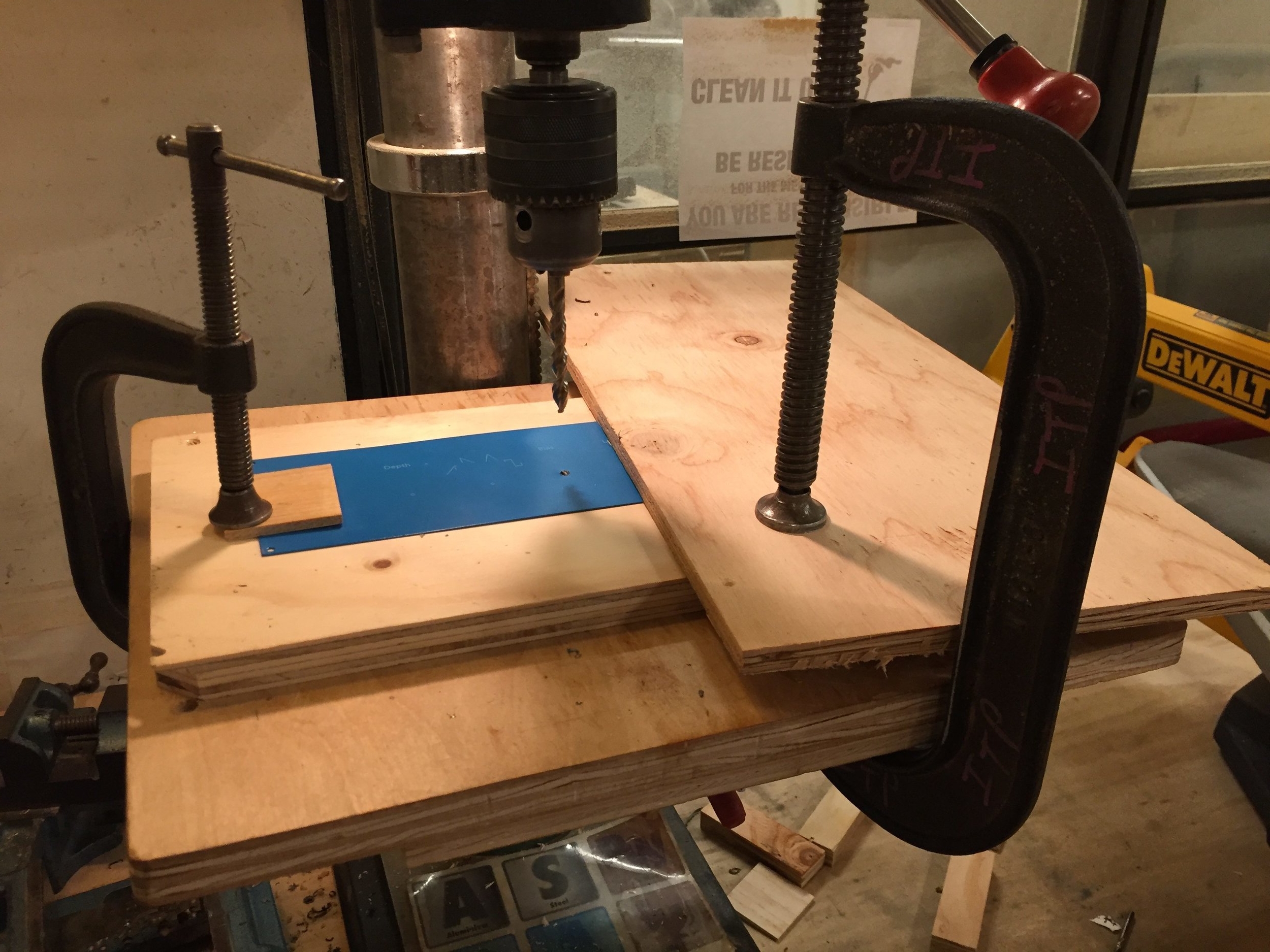
I learned quickly that because of the rigidity and thinness of these metal pieces, both sides of the plate had to be clamped down to get the perfect hole.  One of my holes is a little eaten up because the metal curled up the bit when one side wasn't clamped down as seen in the above picture.

Here is how I made the rest of the holes:

IMG_2771-2-e1480530815113.jpg

Next time, I will bite the bullet and purchase the stepper bit because I'm sure it would have cut my time drilling these holes in half.

The final result
IMG_2774.jpg

Front plate

741B9959.jpg

Back plate

741B9960.jpg

Assignment 3: Laser Cutter

For the second 3rd class of Intro to Fabrications, we were introduced to the laser cutter. We were tasked to try out different materials and spend some time getting familiar with the cutting and etching abilities of the laser cutter.

With the upcoming holidays, I was interested in attempting to make some ornaments for my family.

I'm also interested in working with more raw materials rather than just plastic acrylic.

My Project

I worked on all laser printers 50W, 60W and 75W so I now feel comfortable on all machines.

I decided to use acrylic of two different styles, plain white and marbled white, to create a snowflake ornament that had an etched leather hanging strap.

I decided to use acrylic of two different styles, plain white and marbled white, to create a snowflake ornament that had an etched leather hanging strap.

I used Adobe Illustrator to create swirls for the etched leather

I used Adobe Illustrator to create swirls for the etched leather

This was the end result after many 5 replications on the laser cutter

IMG_9891-e1479340805968.jpg

And here is the acrylic snowflake process:

This is the test cut on cardboard

This is the test cut on cardboard

And here is the actual cut in acrylic:

And here is the actual cut in acrylic:

Here is the end result

Here is the end result

Because the leather wasn't treated and was all black, it was hard to see the etching on the hanging tie, so I may not do that the next time.

I did enjoy working with leather in this instance and will try to think of another applications where the usage of the laser cutter is more obvious.

Assignment 2: Make 5

For our second class in Introduction to Fabrications, we were asked to create five identical items using the tools that we learned about in our second lecture. The lessoned to gain from this concept is to form an appreciation of guides, jigs and an understanding of how to use these procedures in creating multiple version of the same item.

Since I needed to make five of something, I wanted to build an items that is usable so to avoid it simply being thrown in the trash after the class was finished.

I'm an individual that is driven to create visual media and stories and I feel that the ascetic in this form of expression is very important.  With that said, about a month ago, I went to ITP's equipment room to rent out a camera, tripod and tripod dolly to document one of my assignment.  To my surprise, our equipment room didn't have any dollies.  This made me sad, because I really like a moving shot in the scene.  It adds elegance and complexity to a shot --- something that a static shot can't always capture. Here's an example shot where a dolly is used, if you are unfamiliar with what a dolly shot might look like: https://www.youtube.com/watch?v=KSa63M5z1B8.

When I heard about this assignment, I thought this could be a great opportunity to create something that I can use for myself and then donate the other 4 to the equipment room at ITP.

I started looking online and found this amazing folding tripod dolly.

I thought to myself that this would be an easy project to replicate, but adopt slightly.

The short of the story is that  it turned out to NOT be an easy project, even with the guide from that website. It took many days of work and rethinking to pull off the five tripod dollies.  Below is my documentation of the process:

Creating the Tripod Dollies

Equipment:

Sanding belt

Sanding belt

Drill Press

Drill Press

Mitter Saw

Mitter Saw

Day 1: Cutting and Gluing

IMG_2627.jpg

Cut wood for 5 dollies

IMG_2622.jpg

gluing the feet at different levels so that the dolly can collapse for easy storage

IMG_2629-e1478650163360.jpg

Day 2: Finalizing the legs

IMG_0197.JPG.jpeg

These are the 5 tripods cut out and sanded.  I realized that each piece needs to have a small gap, as seen this in picture, so that the legs can swing out from their collapsed state.

IMG_0201.JPG.jpeg

When I added the gap between the different legs, as you can see in this image, the legs no longer line up.  I didn't take into consideration the gap when I first cut the pieces. Mistake #1 for this project.

IMG_2630.jpg

I explained my issue to a classmate, Lindsey Piscitell, and she mentioned that I should simply cut two pieces of wood that would create the gap needed between the legs when stacked and then cut the ends with the Mitter saw so that they line up.  This photo illustrates that concept.

IMG_2631.jpg

After cutting the legs, I used the drill press to drill a hole where the legs will rotate to open up into the triangle shape.

Day 3: Hardware

IMG_2637-1.jpg
IMG_2639.jpg

I couldn't find bolts that were the exact size that I needed for the dolly.  I needed 3.5" bolts and all I could find in hardware store around NYC were 3" or 4".  So I used Ben Light's tutorial on how to cut these to size.

I ended up using washers in between each leg, on the top of the dolly and on the bottom to help with the longevity of the pivoting hole.  My initial concern was that if I simply have a regular nut at the underside of the dolly, that it would become loose and the dolly wouldn't be as stabilized. I picked up some wing nuts so that the user of the dolly could tighten the pivoting joint or loosen it to collapse it. 

IMG_2644-e1478720585383.jpg

Here is mistake #2. When drilling the wheels in with a hand drill, it split the wood on the feet of the dolly

IMG_2646-1-e1478721017583.jpg

I'm not sure if this issue occurred as a result of (1) because I used Pine which apparently a wood that splits easily, or (2) becuase the wheel plate holes were too close to the edge of the foot, or (3) because I used a aggressive drill to insert these screws, or (4) because of a combination of all of the above, but I needed to troubleshoot this issue quickly because I had already spent 2 days making these.

Luckily, I only attached the wheel to one of the legs as a test, so I only had to fix one leg as a result.

IMG_2647.jpg

I traveled to a hardware store near by and picked up a smaller wheel and decided to pre drill the holes and screw them in with a hand-held screw driver to avoid the issue from above occurring again.

This ended up working really well, so I got to move on the drilling the sunken holes in the top of the dolly legs where the tripod feet would rest.

I used a Forsner bit to create the sunken holes.  I drilled one hole on each leg 1" from the end because that was the perfect length for the tripod to be stabilized on the dolly. I also drilled a second sunken hole on the legs, closer to the center so that a smaller tripod could also be used on the dolly.

IMG_2642.jpg
IMG_2643-e1478720551716.jpg

This is what the sunken holes look like on the legs

The end result

After a lot of sanding, this is what I have to show...

After a lot of sanding, this is what I have to show...

collapsed dolly

collapsed dolly

A short tripod using the shallower sunken holes

A short tripod using the shallower sunken holes

An extended tripod using the outer most sunken holes

An extended tripod using the outer most sunken holes